Drag Reduction
Sonic Boom
Shock Wave Boundary Layer Interaction
Drag Reduction
About
この速度を超音速と呼びますが,超音速で飛行すると現在の航空機よりもはるかに燃費が悪くなってしまうという問題点があります.
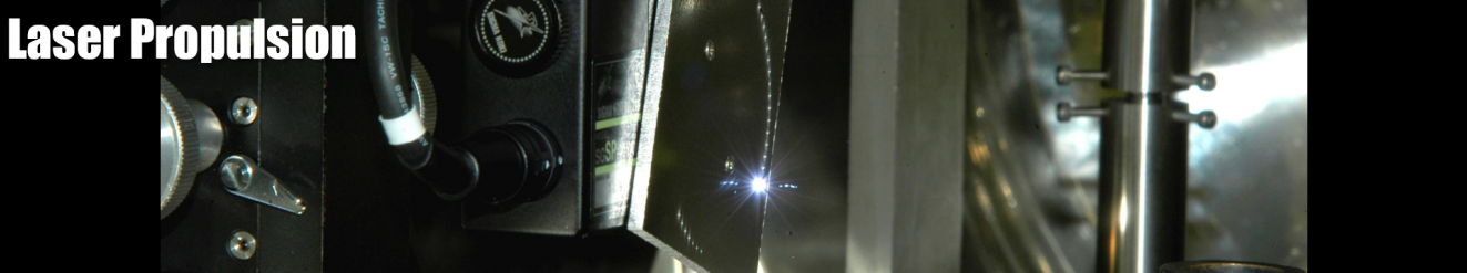
この問題を解決する方法としてレーザーで空気を加熱するという方法が提案されており,この研究室ではこの方法を使ってより効率よく超音速で飛行する方法を研究しています.
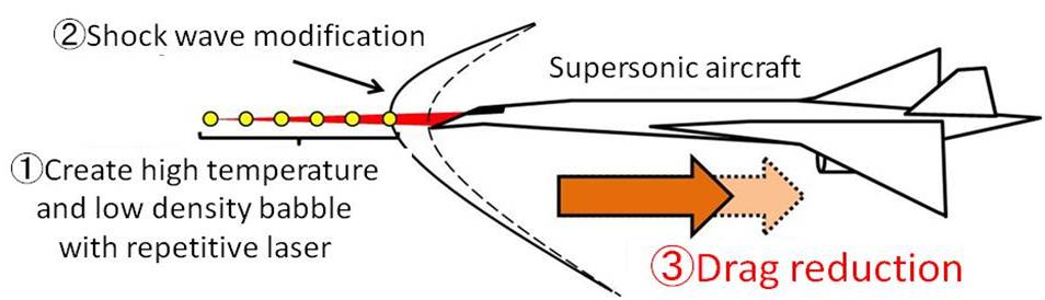
図1 超音速機の抵抗低減方法
研究内容
本研究では,コンコルド以来運用していない超音速旅客機の復活を目指して研究を行っています.コンコルドの運用が中止された原因の1つに,燃費の悪さがあります.超音速航行時では機体から衝撃波が発生してしまい,これによって亜音速飛行時には発生しなかった造波抵抗が発生してしまいます.抵抗が増加することにより,燃費が悪化してしまうのです.
そこで本研究では,繰返しレーザーパルスを用いて低密度場を生成して衝撃波と干渉させることで抵抗を低減し,超音速機の空力性能を向上させることを目指しています.この方法を”Fly By Light Power (FBLP)”と呼称し,実験と数値計算の両面から研究を進めています.
これまでの成果
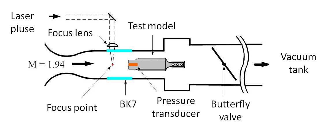
図2 実験装置概略図
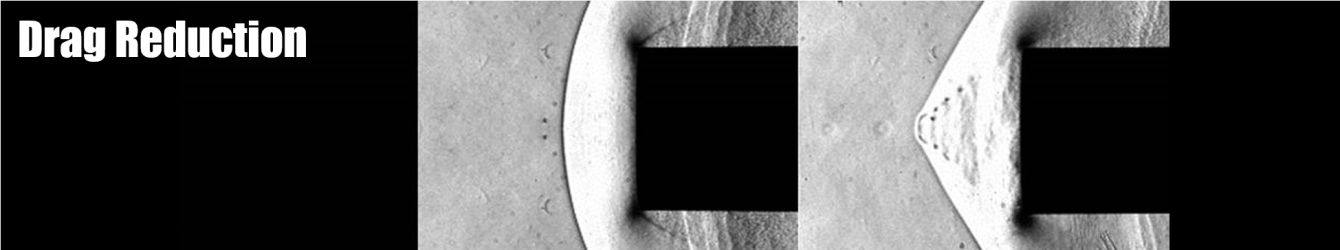
実験には,本研究室で作製した吸い込み式の超音速風洞を用います(図2).マッハ数1.94の風洞内に直径20mmの円柱模型を設置することで,模型前方に弓状衝撃波を発生させ,衝撃波の上流側には繰返しレーザーパルスを用いて低密度バブルを生成させました.その結果,両者の干渉によって衝撃波の変形が見られ,これによって低減した抗力を模型後方のロードセルで測定したところ,定常状態における抵抗が20%低減し,このときのエネルギー付与効率はη=10に達することを確認しました(図3~5).これは数値計算により,バロクリニック効果で生じる渦が抵抗低減に関して大きな影響を与えていることが分かりました.
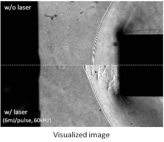 図3 弓状衝撃波の変形 |
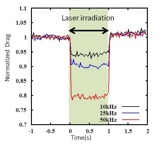 図4 抗力時間履歴 |
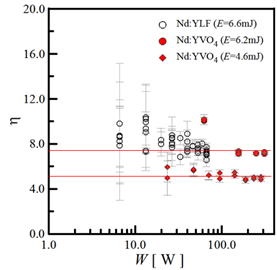 図5 エネルギー付加効率 vs.投入エネルギー |
なぜ抵抗が減るのか?
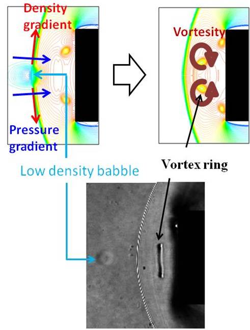
図6 バロクリニック効果 |
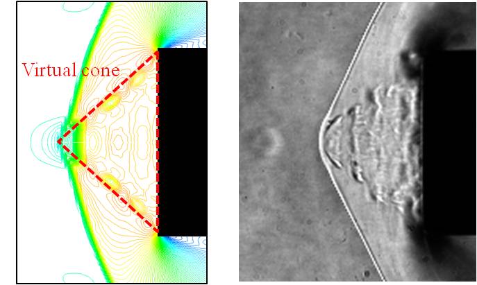
図7 Virtual cone |
レーザーの発振周波数を大きくして,高繰返しで低密度バブルと衝撃波を干渉させると,多くの渦輪が模型前方に滞留し,virtual coneと呼ばれる領域を形成します(図7).Virtual coneは模型前方にあたかも円錐が存在するかのように流れを変化させ,衝撃波の形状を変化させます.これによって衝撃波は減衰し,航空機にかかる抵抗は低減することができるのです.
blunt-cylinder body
0kHz laser energy deposition
80kHz laser energy deposition
関連論文
- T. Sakai, Y. Sekiya, K. Mori, and A. Sasoh, Proceedings of the Institution of Mechanical Engineers, Vol. 222, Part G: Journal of Aerospace Engineering, pp. 605-617, 2008.
- Sakai,T,”Supersonic Drag Performance of Truncated Cones With Repetitive Energy Depositions “,The International Aerospace Innovation , Vol. 1, No. 1, pp. 31-43, 2009.
- Akihiro Sasoh,Yohei Sekiya,Takeharu Sakai,Jae-Hyung Kim and Atsushi Matsuda, AIAA Journal, Vol. 48, No. 12, 2010, pp. 2811-2817.
- Jae-Hyung Kim, Akihiro Sasoh and Atsushi Matsuda, Shock Waves, Vol. 20, pp.339-345, 2010.
- Jae-Hyung Kim, Atsushi Matsuda, Takeharu Sakai, Akihiro Sasoh, AIAA Journal, Vol. 49, No. 9, pp. 2706-2078, 2011.
- Jae-Hyung Kim, Atsushi Matsuda, Akihiro Sasoh, Physics of Fluids, Vol. 23, ArtID 021703,2011.
- Iwakawa A., Sakai T., Sasoh A., Transactions of the Japan Society for Aeronautical and Space Sciences, Aerospace Technology Japan, Vol. 11, pp.53-66, 2013.
- Sasoh S., Kim J. H., Yamashita K., and Sakai T, Shock Waves Vol. 24, No. 1, pp. 59-67, 2014.
- 岩川輝,大須賀健,摩嶋亮祐,酒井武治,佐宗章弘, 日本航空宇宙学会論文集,Vol. 62, pp. 99-106, 2014.
Sonic boom
About
ソニックブーム
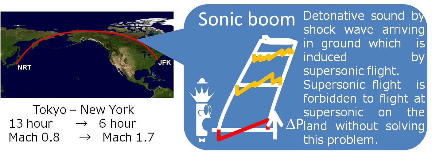
図1 ソニックブーム
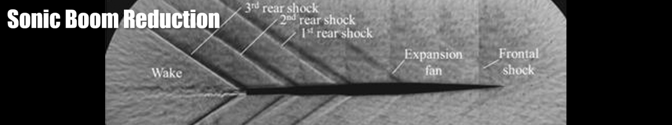
超音速航行時に機体各所から発生した圧力波は大気中を伝播する間に整理統合され,1つの大きな圧力波として地上へ到達しますが,この圧力波は人の耳には大きな爆発音として聞こえます.この一連の現象のことをソニックブームと呼びます.ソニックブームによる騒音のため,現在陸地の上空を超音速で飛行することは基本的に禁止されているため,超音速旅客機を実現するためには騒音低減が必要不可欠となっています.
バリスティックレンジを用いた実験
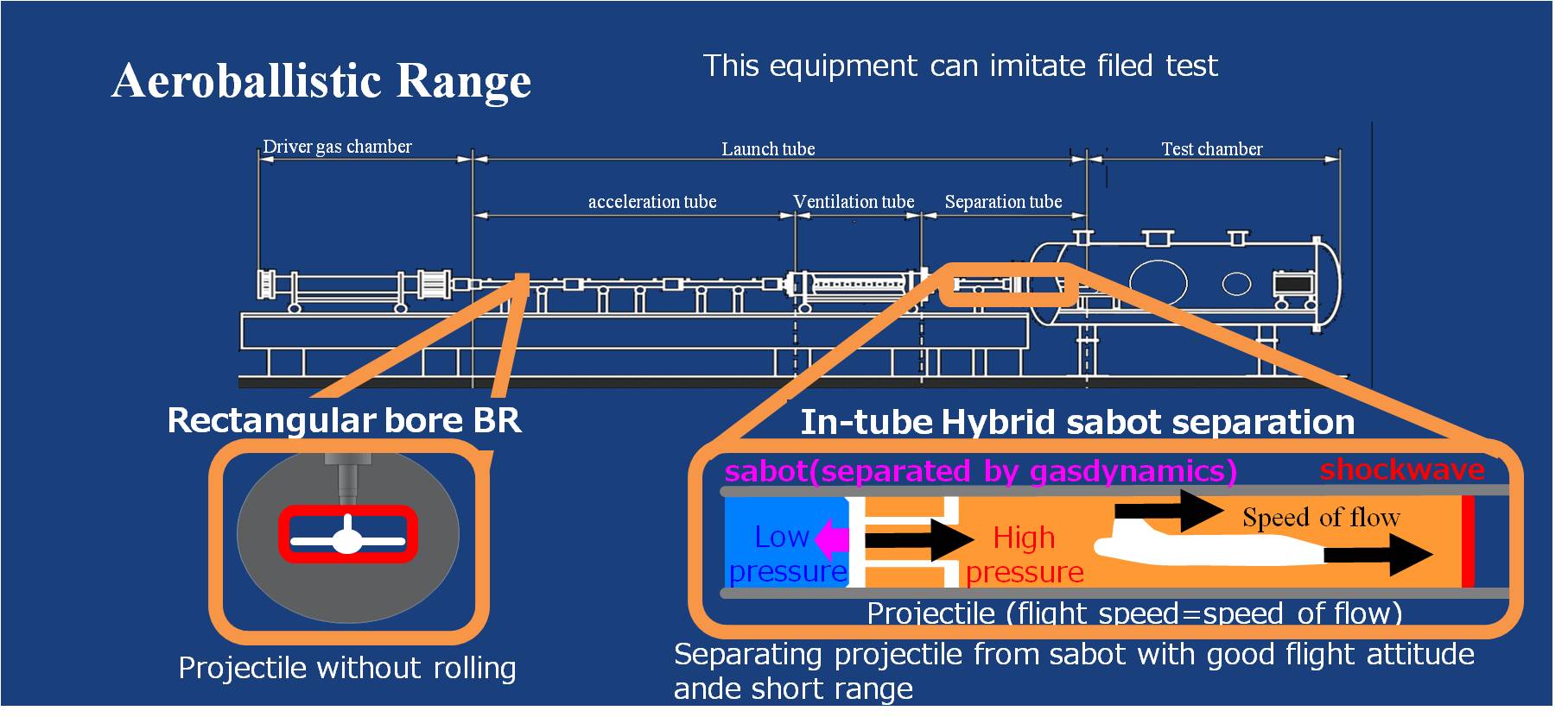
図2 バリスティックレンジ
多段階断面積変化による後端ブーム緩和
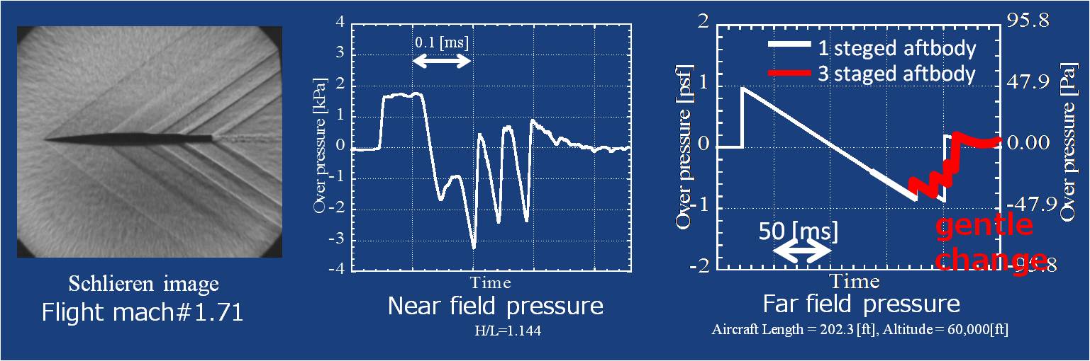
その特徴を生かし,後端からの圧力波に着目して後端に段々をつけることで,段がついていないものよりも緩やかに時間変化する圧力波形を得ることができました.
関連論文
- Akihiro Sasoh and Shin Oshiba, Review of Scientific Instruments, Vol. 77, No. 10, ArtID 105106, 2006.
- Sasoh Akihiro, Takahiro Imaizumi, Atsushi Toyoda, Takeshi Ooyama, AIAA Journal, Vol.53, No.9, pp. 2781-2784, 2015.
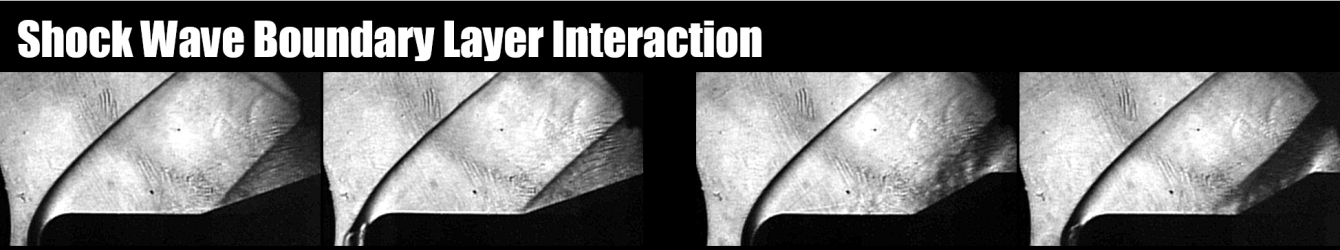
Shock Wave Boundary Layer Interaction
About
超音速での飛行における問題には,抗力の増大やソニックブームの他に衝撃波-境界層干渉(Shock Wave-Boundary Layer Interaction)といわれる現象があります.この現象は機体表面から生成する境界層と音速を超えて飛行するため生じる衝撃波が干渉することにより起こります.この干渉領域内では,衝撃波背後の高圧が境界層内を伝播して境界層の逆圧力勾配を強め,境界層の剥離や剥離に伴う非定常な流れ場が作られてしまい,エンジンの効率の低下や機体の制御を難しくさせる原因となります.
我々の研究室では,衝撃波-境界層干渉における境界層の剥離や非定常な流れをレーザーエネルギー付加という手法を用いて制御を行う研究をしています.
軸対称Cyliner-Flareモデルを用いた風洞実験
本研究室での風洞実験では図1のような軸対称Cyliner-Flareモデルを用いており,Cylinder部分から境界層が発達し,Flare部分により生じた衝撃波と干渉することで,衝撃波-境界層干渉領域が生成します.このようにして作られた衝撃波-境界層干渉に対してレーザーエネルギー付加を行い流れ場の制御を行います.レーザーエネルギー付加は図2のようにモデル前方に生成する弓状衝撃波の上流に高繰り返しで出力されるレーザー光を集光させ,それにより生じた高温低密度の領域を流れに乗せて衝撃波-境界層干渉領域へと運ぶことで行います.
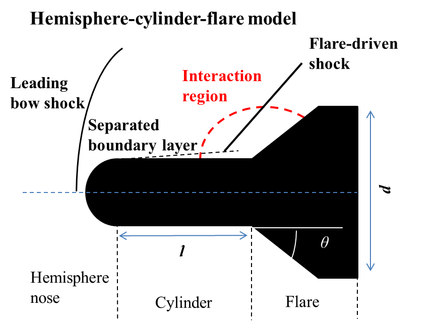
図1 軸対称Cyliner-Flareモデル
図2 レーザーエネルギー付加
これまでの研究結果
本研究室では軸対称Cyliner-FlareモデルのFlare角度を変化させて様々な条件の衝撃波-境界層干渉領域をつくり,それに対してどのようなレーザーエネルギー付加の影響があるのかを実験により検証を行いました.図3にはレーザーエネルギー付加を行った場合と行っていない場合のシュリーレン画像を示します.こららの画像からはエネルギー付加を行うとSlip Lineが無くなっていることが確認され,境界層の剥離が抑制されていることがわかりました.
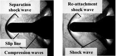
レーザーなし f=60kHz
30度のフレア角場合ー境界層剥離の抑制
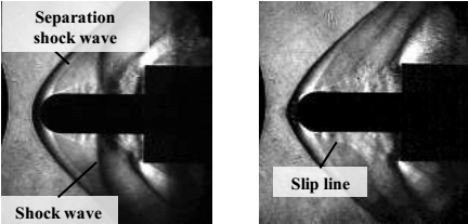
レーザーなし f=60kHz
90度のフレア場合ー貫流振動の抑制
図3 貫流の制御
関連論文
- T. Osuka, E. Erdem, N. Hasegawa, R. Majima, T. Tmaba, S. Yokota, A. Sasoh, K. Kontis, Shock Waves, Vol. 26, No. 9, ArtID 096103, 2014.
- T. Tamba, H. S. Pham, T. Shoda, A. Iwakawa, A. Sasoh, Physics of Fluid, Vol. 27, 091704, 2015.
Drag Reduction
Sonic Boom
Shock Wave Boundary Layer Interaction
Drag Reduction
About
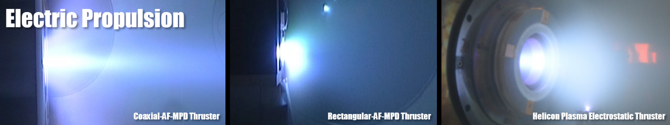
The velocity which is faster than sound is called supersonic. The problem of the supersonic flight is its poor aerodynamic performance.
In order to solve this problem, it is proposed to heat air with laser. Our laboratory is researching on how to make more efficient supersonic flight by using this method.
Fig.1 Drag reduction method for SST(Super Sonic Transportation)
About reserach
The goal of this investigation is to realize a commercial supersonic transportation which has not been operated after the abortion of Concorde. One major reason that led to the abortion of Concorde was its poor performance of fuel efficiency. The large wave drag caused by shock waves is occurred during supersonic flight. This drag does not exist during subsonic flight. This drag increment leads to worsen the fuel efficiency.
The objective of this investigation is to improve the aerodynamics performance of supersonic transportation by using the interaction between low density bubbles generated by repetitive laser pulses and shock waves. This method is called “Fly by Light Power(FBLP)” and we are approaching our reserach from two perspectives: experimental and numerical investigations.
Current outcome
Fig.2 Experimental apparatus
The supersonic wind tunnel that we use for our experiment is designed by students in our laboratory(Fig.2). The test model is 20mm diameter cylinder. Bow shock made by Mach 1.94 flow and low density babble generated by laser irradiation interacts. This interaction makes bow shock moderate and creates vortex rings. This phenomena decreases the drag of the cylinder model about 20%, and the η(energy deposition efficiency) reached 10(Fig.3~5). From numerical simulation, it has been found that vortex rings generated by baroclinic effect have large effect on for drag reduction mechanism.
|
|
Fig.5 energy deposition efficiency vs.input energy |
How to Drag Reduction?
|
|
Fig.7 Virtual cone |
By increasing repetitive frequency of laser, more vortex rings stay in front of the test model . It creates the area which called ‘Virtual cone’(Fig.7). Virtual cone acts as cone attached in front of the cylinder test model. It makes bow shock attenuation. Consequently it reduces the drag.
blunt-cylinder body
0kHz laser energy deposition
80kHz laser energy deposition
Related Journal
- T. Sakai, Y. Sekiya, K. Mori, and A. Sasoh, Proceedings of the Institution of Mechanical Engineers, Vol. 222, Part G: Journal of Aerospace Engineering, pp. 605-617, 2008.
- Sakai,T,”Supersonic Drag Performance of Truncated Cones With Repetitive Energy Depositions “,The International Aerospace Innovation , Vol. 1, No. 1, pp. 31-43, 2009.
- Jae-Hyung Kim, Akihiro Sasoh and Atsushi Matsuda, Shock Waves, Vol. 20, pp.339-345, 2010.
- Jae-Hyung Kim, Atsushi Matsuda, Takeharu Sakai, Akihiro Sasoh, AIAA Journal, Vol. 49, No. 9, pp. 2706-2078, 2011.
- Jae-Hyung Kim, Atsushi Matsuda, Akihiro Sasoh, Physics of Fluids, Vol. 23, ArtID 021703,2011.
- Iwakawa A., Sakai T., Sasoh A., Transactions of the Japan Society for Aeronautical and Space Sciences, Aerospace Technology Japan, Vol. 11, pp.53-66, 2013.
- Sasoh S., Kim J. H., Yamashita K., and Sakai T, Shock Waves Vol. 24, No. 1, pp. 59-67, 2014.
- 岩川輝,大須賀健,摩嶋亮祐,酒井武治,佐宗章弘, 日本航空宇宙学会論文集,Vol. 62, pp. 99-106, 2014.
Sonic boom
About
Sonic Boom
Fig.1 Sonic Boom
When air planes flight at supersonic, shockwaves, expansion waves and other disturbances are induced. These are integrated in contagious process and the detonative sounds are observed on the ground. This phenomenon is called sonic boom. Because of the noise produced by sonic boom, supersonic flight is forbidden on the land. Therefore, reducing this noise is imperative to develop next generation supersonic transports.
Experiment with Ballistic Range
Fig.2 Ballistic Range
Sonic Boom reduction with staged aft body
Fig.3 Sonic Boom reduction with staged aft body
Using this characteristic, we could demonstrate the reduction of rear sonic boom by experiments.
Related Journal
- Akihiro Sasoh and Shin Oshiba, Review of Scientific Instruments, Vol. 77, No. 10, ArtID 105106, 2006.
- Sasoh Akihiro, Takahiro Imaizumi, Atsushi Toyoda, Takeshi Ooyama, AIAA Journal, Vol.53, No.9, pp. 2781-2784, 2015.
Shock Wave Boundary Layer Interaction
About
Shock wave and boundary layer Interaction (SWBLI) causes many serious problems to supersonic flight, such as unsteadiness of flow which leads to a decrease of engine performance, wing lift capacity and control surfaces effectiveness, as well as heat transfer and pressure loads which reduce the endurance of aircraft structures. To realize future supersonic transport, one of the important missions is to minimize negative impacts of SWBLI on supersonic vehicle.
Experimental approach
SWBLI was investigated by experimental approach. The hemisphere nose-cylinder-flare model configuration was used to study the interaction between the boundary layer of cylinder surface and the shock wave generated by flare part (Fig. 1). The adverse pressure from the flare-driven shock propagates upstream and leads to separated boundary layer as well as flow unsteadiness. Length of cylinder, angle and diameter of flare are changeable to achieve several of interaction states.
Fig. 1 SWBLI model configuration
Laser Energy Deposition (LED) method on flow control
In this study, we used LED as an active method to control the flow (Fig. 2). In detail, we took advantage of the low-density-bubble created by high repetitive laser pulses to suppress the separated boundary layer. By using LED, these bubbles interacted with the leading shock and transformed to vortex rings. In the next steps, the disturbance introduced by these rings induced the boundary layer transition so that it became “robust” against the adverse pressure gradient. Osuka et al. (2014).
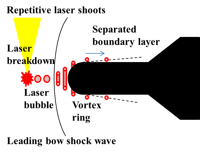
Fig. 2 Boundary layer modification by LED method
Flow control by LED
Using high repetitive laser with frequency up to 60 kHz, the LED method shows its effectiveness in separation control in case of weak interaction, corresponding to small-flare-angle model (Fig. 3). Besides, in case of strong interaction, the LED method shows the ability to reduce oscillation of flow (Fig. 4). Future studies will focus on the low-frequency unsteadiness which plays an important role to the structure fatigue by resonant pressure load.
w/o LED f=60 kHz
Fig. 3 Separation control
w/o LED f=60 kHz
Fig. 4 Oscillation control
Related Journal
- T. Osuka, E. Erdem, N. Hasegawa, R. Majima, T. Tmaba, S. Yokota, A. Sasoh, K. Kontis, Shock Waves, Vol. 26, No. 9, ArtID 096103, 2014.
- T. Tamba, H. S. Pham, T. Shoda, A. Iwakawa, A. Sasoh, Physics of Fluid, Vol. 27, 091704, 2015.